3. CHAPTER 3: FLO-2D Storm Drain Data Files
3.1. Input and Output File - General
This chapter describes the input and output data and their format for the FLO-2D storm drain component. The storm drain input data files can be created using any storm water user interface GUI:
FLO-2D QGIS plug-in,
EPA SWMM 5,
inpPINS,
Storm and Sanitary Analysis.
The following folders contain the storm drain model system:
FLO-2D PRO folder in C:\Program Files (x86). All executable program files for the FLO-2D model including pre- and post-processing and FLOPRO.exe are in this folder.
FLO-2D PRO documentation folder in C:\Users\Public\Documents\FLO-2D PRO Documentation (My Documents). Manuals, Handout Documents, PowerPoint Presentations, and tutorials are in this directory. Online documentation site: https://documentation.flo-2d.com/
3.2. Data Input Files
The FLO-2D data input files are generated by the QGIS plug-in. The QGIS plug-in creates all the storm drain data files, for more information review the FLO-2D Plugin User’s Manual document.
Typically, the FLO-2D grid system is prepared prior to developing the storm drain model. The QGIS tool creates the SWMM.inp file from a set of shapefiles (see FLO-2D Plugin User’s Manual document for more details) and pairs the inlets with grid elements. QGIS plug-in creates the associated storm drain data files needed for a FLO-2D Storm Drain simulation (SWMMFLO.DAT, SWMMOUTF.DAT and SWMMFLORT.DAT).
The following data files must be created to run a FLO-2D storm drain simulation:
3.2.1. CONT.DAT
This file contains the simulation control parameters:
Set SWMM = 1 to initiate the storm drain component, review the DATA INPUT MANUAL.DAT file for more information about this switch.
For no storm drain simulation, SWMM = 0 (default).
3.2.2. SWMM.inp
SWMM.inp is the input file that contains most of the storm drain project data. It includes pipe network geometry, inlet/outlet and junction locations, simulation control settings and hydraulic routing properties. The pipe network components in SWMM.inp must be created with QGIS plug-in or other third-party storm drain software like SWMM GUI. Table 5 lists the section data in the SWMM.inp file. Each section of the SWMM.inp file begins with a keyword.
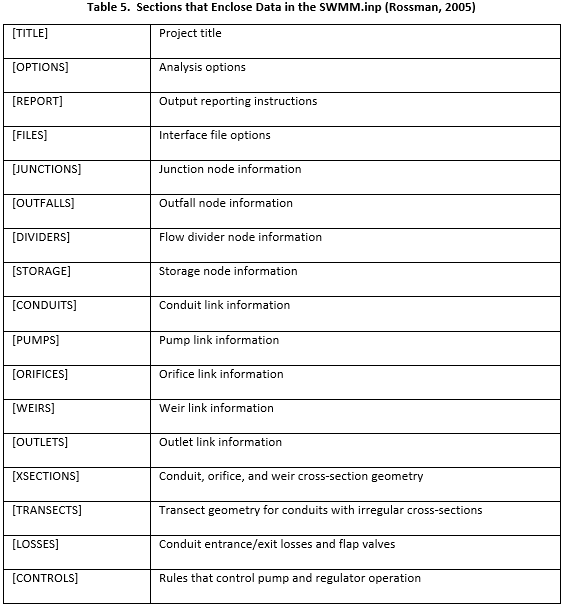
The structure of the SWMM.inp file follows:
Sections appear in any arbitrary order in the input (*.inp) file. Section keywords can appear in mixed lower- and upper-case letters. Only the first four characters (plus the open bracket) are used to distinguish one keyword from another (e.g., [DIVIDERS] and [Divi] are equivalent).
Not all sections must be present on each project.
Each section can contain one or more lines of data.
Blank lines may appear anywhere in the file.
A semicolon (;) can be used to indicate that comment follows, not data. This sometimes generates reading errors in the storm drain code.
Data items can appear in any column of a line.
The data is ordered creating a tabular appearance complete with column headings.
When listing the format of a line of data, mandatory keywords are shown in boldface while optional items appear in parentheses.
A list of keywords separated by a slash (YES/NO) means that only one of the words should appear in the data line.
In the [OPTIONS] section, flow units can be selected as either cubic feet per second (CFS), gallons per minute (GPM), million gallons per day (MGD), cubic meters per second (CMS), liters per second, (LPS), or million liters per day (MLD). If cubic feet or gallons are chosen for flow units then US units are used for all other quantities. If cubic meters or liters are chosen, then metric units apply to all other quantities. The default flow units are CFS.
3.2.3. SWMMFLO.DAT
A node must have an ID starting with an ‘I’ to differentiate the inlet from a junction. Surface water discharge is only shared between nodes that have the correct ID assigned in the *.inp file. Inlets are automatically paired by the QGIS plug-into a corresponding FLO-2D grid element. The SWMMFLO.DAT file contains the inlet geometry as well as the names or numbers that identify inlet paired with the grid cell (Table 6).

The Table 7 outlines the required data in the SWMMFLO.DAT.
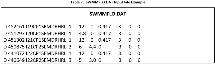
Table 8 lists the variable descriptions for the SWMMFLO.DAT file:
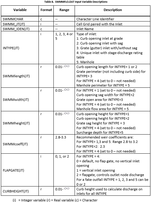
QGIS plugin creates the SWMMFLO.DAT file, review FLO-2D Plugin User’s Manual and FLO-2D Plugin Technical Reference Manual for more information.
3.2.4. SWMMOUTF.DAT
This file lists the outfall data, including the name of the outfall, the grid paired with the outfall and the switch (0, 1 or 2) that allow the flow to discharge to the surface (1 and 2) or out of the system (0).
QGIS plugin creates the SWMMOUTF.DAT file, review FLO-2D Plugin User’s Manual and FLO-2D Plugin Technical Reference Manual for more information.
The required data in the SWMMOUTF.DAT is shown in Table 9 and Table 10:
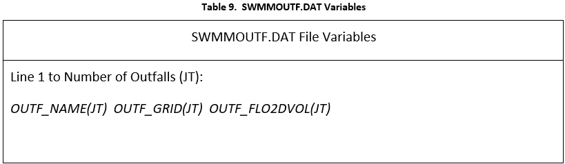
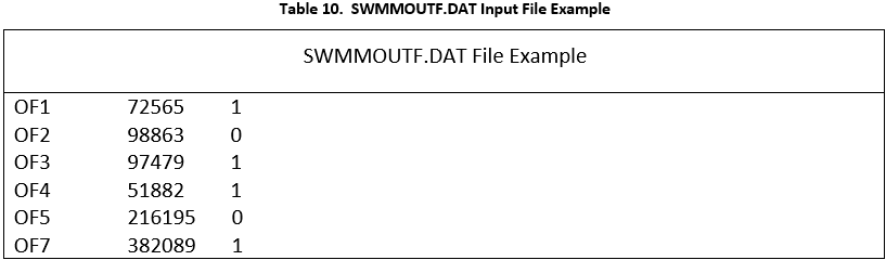
Table 11 lists the variables and the description for the SWMMOUTF.DAT file:
Table 11. SWMMOUTF.DAT Input Variable Descriptions
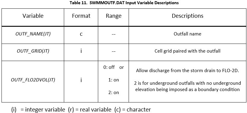
SWMMOUTF.DAT file should contain the list of outfalls in the same order as it appears on the SWMM.inp. When the outfall order is modified in the SWMM.inp file because an outfall node was added or deleted, the list of outfall nodes in the QGIS plug-in should be edited and the SWMMOUTF.DAT file saved. The functionality of the outfall nodes is as follows:
If the outfall discharge is ‘off’ the outfall will discharge off the complete model system. No discharge is returned from the storm drain to the surface water.
If the outfall discharge switch is ‘on’ the surface water elevation and storm drain pressure head are compared and the outfall will discharge until WSE is equal or greater than the storm drain head. The outfall flow drains back to the surface water.
Potential backflow into the outfall pipe will depend on the comparison of the WSEL, the storm drain pressure head and the tide gate assignment.
3.2.5. SWMMFLORT.DAT
The SWMMFLORT.DAT file contains a list of the rating table data or the culvert data only for those inlets that are non-typical inlets assigned as Type4 in the storm drain system.
QGIS plugin creates the SWMMFLORT.DAT file by automatically reading the rating table from a file for each inlet type 4. Culvert data can also be added for inlets type 4. The generalized culvert equation with inlet control will be used to calculate the discharge from the surface entering the inlet. For more detailed information review the FLO-2D Plugin User’s Manual and the FLO-2D Plugin Technical Reference Manual.
The rating table is used throughout the simulation without adjustment.
The structure of a SWMMFLORT.DAT file is:
ID Grid Cell
ID Depth Discharge
ID Depth Discharge
ID Depth Discharge
…
The first pair of numbers should be zero depth and zero discharge. This is repeated from 1 to number of storm drain inlets with INTYPE= 4 (Table 12).
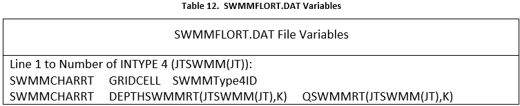
The required data in the SWMMFLORT.DAT is listed in Table 12 and Table 13.
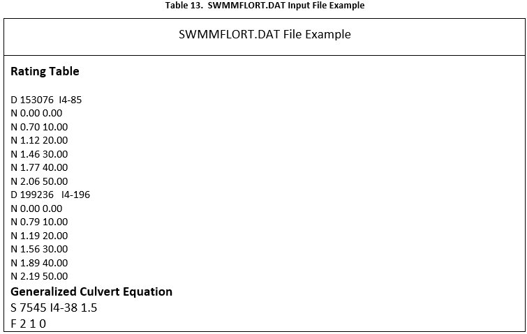
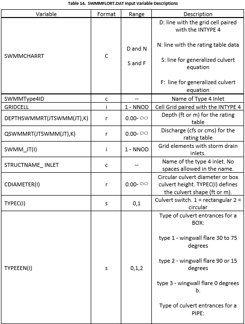
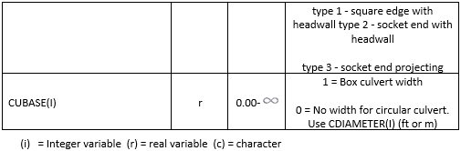
Table 14 lists the description of the variables for the SWMMFLORT.DAT file.
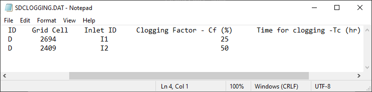
3.2.6. SDCLOGGING.DAT
A clogging factor was created to simulate the debris reduction of the inlet capacity.
QGIS plugin creates the SDCLOGGING.DAT file for inlet type 1,2,3,4 or 5. For more detailed information about the methodology review the FLO-2D Plugin User’s Manual and the FLO-2D Plugin Technical Reference Manual.
This option (INTYPE = 1,2,3,4 or 5 in the SWMMFLO.DAT) is assigned by the QGIS in the inlet geometry dialog box.
The SDCLOGGING.DAT file contains the data with the following format:
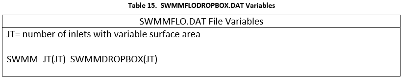
SWMMFLODROPBOX.DAT
A file was created to enter variable dropbox surface area for inlets in the storm drain system. A minimum nodal surface area of 12.566 ft2 (~4 ft diameter) is hardwired in the SD code for drop box surface areas. A new file named SWMMFLODROPBOX.DAT can be used to enter spatially variable sizes inlet drop boxes. If this file exists, the minimum surface area is replaced by the drop box surface area entered in the file named SWMMFLODROPBOX.DAT.
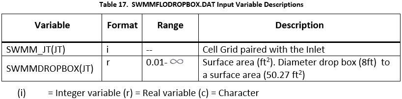
The Table 7 outlines the required data in the SWMMFLODROPBOX.DAT.
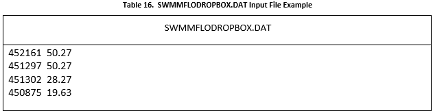
Table 8 lists the variable descriptions for the SWMMFLODROPBOX.DAT file:
Table 17. SWMMFLODROPBOX.DAT Input Variable Descriptions
3.2.7. SWMM.ini
After a project is saved in the storm drain GUI, the control settings file SWMM.ini will automatically be generated. This file has the same name as the project file and the extension *.ini. It contains global settings and model output options such as map display, legend colors and intervals, object default values. If the SWMM.rpt and SWMM.out files are in the folder but the EPA SWMM is not loading the results, the user needs to enable the display of results in the storm drain GUI, the user must set the last two lines in Figure 38 as shown.
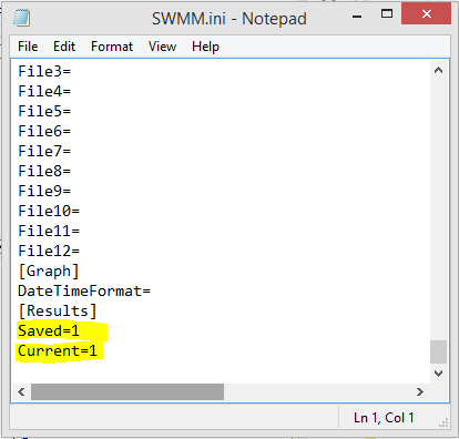
Figure 38. SWMM.ini file.
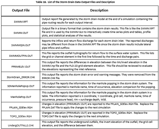
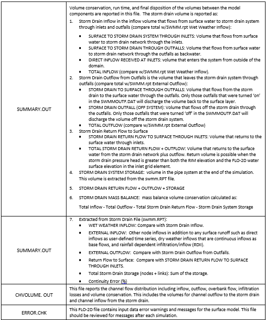
3.3. Output files
With the successful completion of a FLO-2D storm drain simulation, the storm drain output files will be created in the simulation folder. Table 18 list the storm drain output files and the description.